QTR-8A Kızılötesi Çizgi Sensörü Kullanımı ve Basit PID Çizgi İzleyen Robot Yapımı
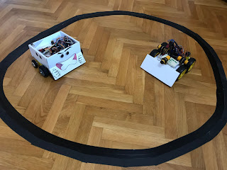
 Bu çalışmamda, çizgi takip eden robotlarda, hızlı çizgi izleme yarışma robotlarında ve labirent çözen robotlarda sıkça kullanılan ve oldukça başarılı bir çizgi sensörü olan Pololu QTR-8A analog çizgi sensörünün nasıl kullanıldığını anlatmaya çalıştım. Örnek olarak da basitçe bir PID çizgi izleyen robot uygulaması gerçekleştirdim. Umarım sizler için faydalı olur.
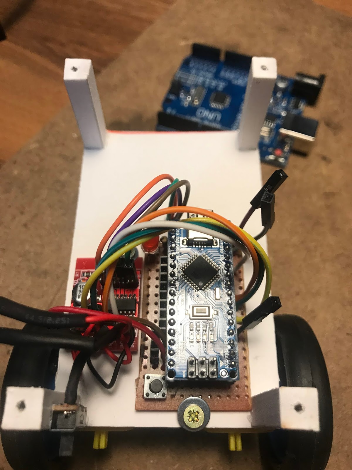


Gerekli Malzemeler:
1 adet Pololu QTR-8A analog çizgi sensörü
1 adet arduino Nano
1 adet L298 motor sürücü kartı
2 adet N20 12mm micro dc redüksiyonlu motor
2 adet tekerlek
1 adet LM2596 voltaj regülatörü
1 adet sw ve jumper kablolar
1 adet sarhoş teker
Pil
Devre Şeması

QTR Kütüphanesi
Arduino Kodu:
QTR KULLANIMI
#include <QTRSensors.h>
QTRSensors qtr;
const uint8_t SensorCount = 8;
uint16_t sensorValues[SensorCount];
void setup()
{
// configure the sensors
qtr.setTypeAnalog();
qtr.setSensorPins((const uint8_t[]){A0, A1, A2, A3, A4, A5, A6, A7}, SensorCount);
// qtr.setEmitterPin(2);
delay(500);
pinMode(LED_BUILTIN, OUTPUT);
digitalWrite(LED_BUILTIN, HIGH); // turn on Arduino's LED to indicate we are in calibration mode
// analogRead() takes about 0.1 ms on an AVR.
// 0.1 ms per sensor * 4 samples per sensor read (default) * 6 sensors
// * 10 reads per calibrate() call = ~24 ms per calibrate() call.
// Call calibrate() 400 times to make calibration take about 10 seconds.
for (uint16_t i = 0; i < 400; i++)
{
qtr.calibrate();
}
digitalWrite(LED_BUILTIN, LOW); // turn off Arduino's LED to indicate we are through with calibration
// print the calibration minimum values measured when emitters were on
Serial.begin(9600);
for (uint8_t i = 0; i < SensorCount; i++)
{
Serial.print(qtr.calibrationOn.minimum[i]);
Serial.print(' ');
}
Serial.println();
// print the calibration maximum values measured when emitters were on
for (uint8_t i = 0; i < SensorCount; i++)
{
Serial.print(qtr.calibrationOn.maximum[i]);
Serial.print(' ');
}
Serial.println();
Serial.println();
delay(1000);
}
void loop()
{
// read calibrated sensor values and obtain a measure of the line position
// from 0 to 7000 (for a white line, use readLineWhite() instead)
uint16_t position = qtr.readLineBlack(sensorValues);
// print the sensor values as numbers from 0 to 1000, where 0 means maximum
// reflectance and 1000 means minimum reflectance, followed by the line
// position
for (uint8_t i = 0; i < SensorCount; i++)
{
Serial.print(sensorValues[i]);
Serial.print('\t');
}
Serial.println(position);
delay(250);
}
PID ÇİZGİ İZLEYEN
#include <QTRSensors.h>
#define Kp 0.4 // Kendi deneyimlerinizle bulmanız gerekli küçük bir değer ile başlayıp, büyütebilirsiniz en kararlı Kp değerini bulana kadar.. 0.4
#define Kd 2 // Bunu da küçük bir değerden başlatın ve deneyimleyerek büyütün. ( Not: Kp < Kd) 2.0
#define rightMaxSpeed 114
#define leftMaxSpeed 115
#define rightBaseSpeed 85 // robot için kp ve kd değerlerini tutturduysanız şayet motorların dönmesi gereken hız budur
#define leftBaseSpeed 86 // yukarıdaki değer ile aynıdır
#define rightMotor1 11
#define rightMotor2 12
#define rightMotorPWM 9
#define leftMotor1 5
#define leftMotor2 6
#define leftMotorPWM 3
QTRSensors qtr;
const uint8_t SensorCount = 8;
unsigned int sensorValues[SensorCount];
void setup()
{
// configure the sensors
qtr.setTypeAnalog();
qtr.setSensorPins((const uint8_t[]){A0, A1, A2, A3, A4, A5, A6, A7}, SensorCount);
pinMode(rightMotor1, OUTPUT);
pinMode(rightMotor2, OUTPUT);
pinMode(rightMotorPWM, OUTPUT);
pinMode(leftMotor1, OUTPUT);
pinMode(leftMotor2, OUTPUT);
pinMode(leftMotorPWM, OUTPUT);
pinMode(LED_BUILTIN, OUTPUT);
digitalWrite(LED_BUILTIN, HIGH); // turn on Arduino's LED to indicate we are in calibration mode
int i;
for (int i = 0; i < 100; i++) { // tercihe bağlı alandır ya robotunuzu hatta yürüterek kalibre edin veya bunu otomatik yapın.
//otomatik kalibrasyon için burasının yorumunu kaldırın
if ( i < 25 || i >= 75 ) {// sensörleri, karşılaşılabilecek en aydınlık ve en karanlık okumalara maruz bırakmak için sola ve sağa çevirin.
turn_right();
} //bu fonksiyonları yazacaz
else {
turn_left();
}
qtr.calibrate();
delay(20);
}
wait(); //motorları durdur
digitalWrite(LED_BUILTIN, LOW); // turn off Arduino's LED to indicate we are through with calibration
delay(1000); // Ana döngüye girmeden önce botu konumlandırmak için 1 saniye bekleyin
}
int lastError = 0;
void loop()
{
// read calibrated sensor values and obtain a measure of the line position
// from 0 to 7000 (for a white line, use readLineWhite() instead)
unsigned int position = qtr.readLineBlack(sensorValues);
int error = position - 3500;
int motorSpeed = Kp * error + Kd * (error - lastError);
lastError = error;
int rightMotorSpeed = rightBaseSpeed + motorSpeed;
int leftMotorSpeed = leftBaseSpeed - motorSpeed;
if (rightMotorSpeed > rightMaxSpeed ) rightMotorSpeed = rightMaxSpeed;
if (leftMotorSpeed > leftMaxSpeed ) leftMotorSpeed = leftMaxSpeed;
if (rightMotorSpeed < 0) rightMotorSpeed = 0;
if (leftMotorSpeed < 0) leftMotorSpeed = 0;
digitalWrite(rightMotor1, HIGH);
digitalWrite(rightMotor2, LOW);
analogWrite(rightMotorPWM, rightMotorSpeed);
digitalWrite(leftMotor1, HIGH);
digitalWrite(leftMotor2, LOW);
analogWrite(leftMotorPWM, leftMotorSpeed);
}
void wait() {
digitalWrite(rightMotor1,LOW);
digitalWrite(rightMotor2, LOW);
digitalWrite(leftMotor1, LOW);
digitalWrite(leftMotor2, LOW);
}
void turn_left() {
digitalWrite(rightMotor1,HIGH);
digitalWrite(rightMotor2, LOW);
analogWrite (rightMotorPWM,rightBaseSpeed);
digitalWrite(leftMotor1, LOW);
digitalWrite(leftMotor2, HIGH);
analogWrite (leftMotorPWM,leftBaseSpeed);
}
void turn_right() {
digitalWrite(rightMotor1,LOW);
digitalWrite(rightMotor2, HIGH);
analogWrite (rightMotorPWM,rightBaseSpeed);
digitalWrite(leftMotor1, HIGH);
digitalWrite(leftMotor2, LOW);
analogWrite (leftMotorPWM,leftBaseSpeed);
}

Hocalarım siteyi paylaşmış, teşekkürler...
YanıtlaSil